The 7-Minute Rule for Wedge Barriers

In the following discussion, recommendation is made to a surface of a structure to which the wedge-style barrier is mounted. In the illustrated embodiments, the upper side of the anchor is substantially flush with the surface area of the foundation. In such embodiments, the wedge-style obstacle may be installed straight to the surface of the foundation. In other personifications, the upper side of the support might be a little elevated over the surface of the structure or somewhat recessed listed below the surface of the structure. 1 is a front viewpoint view of an embodiment of a surface-mounted wedge-style obstacle 10. As shown, the barrier 10 is placed to a surface area 12 of a foundation 14(e. g., a superficial structure ). For instance, the foundation
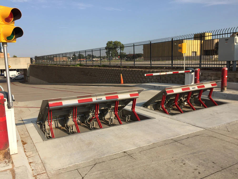
14 and the surface 12 to which the obstacle 10 is protected might be made from concrete - Wedge Barriers. 2, the obstacle 10 is mounted to or includes an anchor or subframe (e. g., support 30 displayed in FIG. 2 )protected under the surface 12. For instance, the bather 10 may be bolted to the support or protected to the anchor by various other mechanical bolts. In the illustrated personification, the barrier 10 consists of a wedge plate 16, that includes a portion that is significantly identical with the surface area 12 when the barrier 10 remains in the withdrawed position. In various other words, vehicles or individuals may overlook the obstacle 10 when the obstacle 10 remains in the pulled back position and experience minor altitude about the surface area 12 while on the barrier 10. As discussed in detail listed below, when the obstacle 10 remains in the released setting, the wedge plate 16 is held and sustained in a raised setting by a training system of the obstacle 10. Additionally, the components 18 might be bolted or otherwise mechanically paired to each other. In this way, repair or substitute of several components 18 might be streamlined and streamlined. That is, repair work or substitute of solitary parts
18 might be done faster, conveniently, and expense efficiently. FIG. In certain embodiments, the anchor 30 might be a steel frame including plates, light beams(e. g., I-beams ), and/or other structures that are safeguarded within the foundation 14, which may be concrete. At the surface 12, an upper side 28 of the support 30 may be at least partly exposed
, thereby making it possible for the accessory of the barrier 10 to the anchor 30. g., threaded openings)in one or even more beams or plates of the anchor 30 may be subjected to the surface area 12. In this manner, screws 32 or various other mechanical fasteners may be made use of to protect the barrier 10 to the support 30. As the obstacle 10 is mounted to the surface 12 of the structure 14, collection of debris and various other material below the obstacle might be lowered, and components of the bather 10 may not be revealed to below quality settings. As suggested by referral numeral 52, the training mechanism 50 includes parts got rid of under the wedge plate 16. For example, the components 52 below the wedge plate 16 may include an electromechanical actuator, a camera, one or even more camera surface areas, and so forth. Furthermore, the training device 50 includes a springtime setting up 54
The springtime rod 58 is coupled to a camera(e. g., webcam 80 received FIG. 4) of the lifting system 50. The springtimes 60 disposed regarding the spring rod 58 are held in compression by spring sustains 62, including a fixed spring assistance 64. That is, the set spring assistance 64 is fixed loved one to the foundation 14 and the rest of the bather 10.
How Wedge Barriers can Save You Time, Stress, and Money.
The continuing to be force used to
the cam camera deploy release wedge plate 16 may be provided offered an electromechanical actuator 84 or other various other. The springtime assembly 54 and the actuator 84(e. Wedge Barriers. g., electromechanical actuator)may operate together to translate the web cam and lift the wedge plate 16.
As discussed over, the spring assembly 54 applies a continuous pressure on the webcam, while the electromechanical actuator may be controlled to put in a variable pressure on the cam, consequently enabling the training and lowering( i. e., deploying and withdrawing )of the wedge plate 16. In specific embodiments, the continuous pressure used by the spring assembly 54 may be adjustable. g., electromechanical actuator) is impaired. As will be appreciated, the spring assembly 54 might be covered and secured from particles or various other components by a cover plate(e. g., cover plate 68 displayed in FIG. 4) that might be substantially flush with the elevated surface area 38 of the foundation 14. As stated above, in the released placement, the wedge plate 16 offers to obstruct accessibility or traveling beyond the obstacle 10. The obstacle 10(e. g., the wedge plate 16 )may block pedestrians or automobiles from accessing a residential property or path. As gone over above, the barrier 10 is attached to the support 30 protected within the foundation 14,
front brackets 71. Therefore, the affiliation assemblies 72 might pivot and revolve to make it possible for the collapse and expansion of the link settings up 72 throughout retraction and deployment of the bather 10. The linkage settings up 72 cause movement of the wedge plate 16 to be limited. If an automobile is traveling in the direction of the deployed wedge plate 16(e. For example, in one situation, the safety legs 86 may be expanded duringmaintenance of the barrier 10. When the safety and security legs 86 are released, the safety legs 86 support the weight of the wedge plate 16 against the surface area 12. As a result, the training system 50 might be shut down, serviced, eliminated, replaced, etc. FIG. 5 is partial perspective view of a personification of the surface-mounted wedge-style barrier 10, illustrating the cam 80 and the camera surface areas 82 of the lifting device 50. Particularly, 2 cam surfaces 82, which are described as lower camera surface areas 83, are positioned below the camera 80. The reduced webcam surface areas 83 might be taken care of to the surface area 12 (e. For instance, the reduced webcam surfaces 83 and the placing plate 85 might develop a single item that is safeguarded to the support 30 by bolts or various other mechanical bolts. In addition, 2 cam surface areas 82, which are described as top cam surfaces 87, are positioned above the cam 80 and coupled to (e. In other embodiments, intervening layers or plates may be placed in between More about the author the surface area 12 and the reduced camera surface areas 83 and/or the wedge plate 16 and the top web cam surface areas 87 As pointed out above, the cam
80 translates my latest blog post along the webcam surface areas 82 when the wedge plate 16 is raised from the withdrawed placement to the released placement. In addition, as mentioned over, the springtime setting up 54 (see FIG. 3 )might offer a force acting on the cam 80 in the instructions 102 through springtime rod 58, which may reduce the pressure the electromechanical actuator 84 is called for to use to the web cam 80 in order to activate and lift the wedge plate 16. 1 )to the deployed position(see FIG. 4). As shown, the cam 80 consists of track wheels 104(e. g., rollers), which call and convert along the web cam surface areas 82 during operation.